|
STK3152mk3 The STK3152mk3 is a very unusual module from Sanyo. It is not a power amplifier per se. Rather, it’s a Voltage Amplifier. As the name implies, it amplifies the voltage only. The end user needs to design the current output stage. This offers professionals greater flexibility in designing a power amplifier. For instance, he can choose to use Bi-polar transistors or power mosfets. He also has the option of using multiple pairs for higher power output. Let’s take a closer look at what the STK3152mk3 is all about. Inside the STK3152mk3
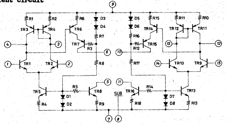
The input differential uses current mirrors (TR3, TR4) as an active load. Standing current is supplied by a current source TR5. After the differential, the signal is injected into the base of TR6. This is the main transistor that amplifies the voltage. This 2nd stage of the circuit is commonly known as the Voltage Amplifier Stage (VAS). Interestingly, there is a cascode (TR7). We can infer from this that they are trying to preserve the quality of the high frequencies. Lastly, the VAS standing current is by another current source (TR8). Since they are using a current source, there’s no boot-strapping like in the STK4241mk2. In other words, there’s no way to adjust the standing current in the VAS. External Components
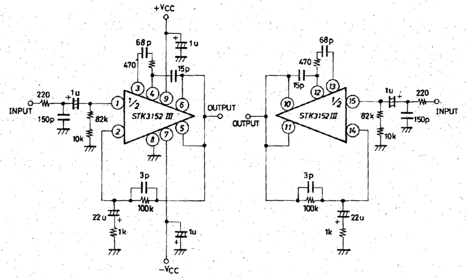
Very few components are needed for the STK3152mk3. There’s the mandatory input filters at PIN 1. Negative feedback is via PIN 2. The 470 ohm resistor in series with the 68pF capacitor across the differential legs (PIN 3, PIN4) are to stabilize the amplifier. Likewise the 15pF across PIN 6 to PIN 4. That’s actually a Miller Compensating cap. The circuit above will not have music. Like I mentioned earlier, it needs a power stage. Completing the Amplifier
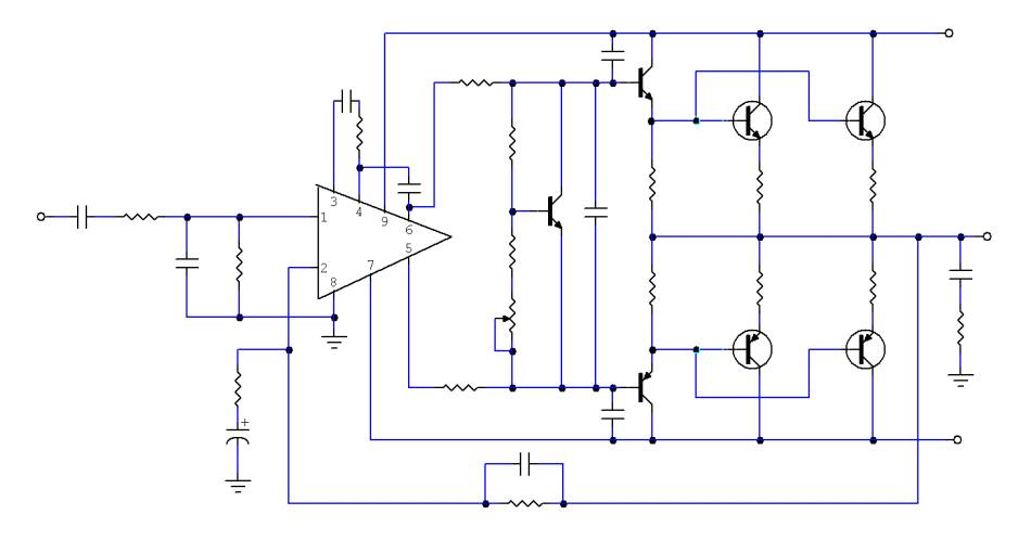
Fig 3 shows the STK3152mk3 in a complete power amplifier. The power transistors I am using are the Toshiba 2SC5200 and 2SA1943. With 2 pairs, I am expecting 200W into 4 ohms. This power output is far greater than what can be achieved from a STK amplifier. This is where the value of the STK3152mk3 is. STK3152mk3 Power Amplifier PCB
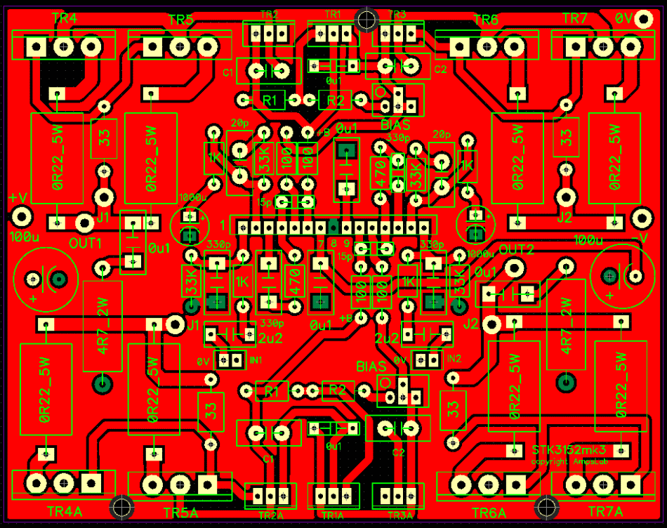
Fig 4 is a complete 2-channel power amplifier using the STK3152mk2. All the transistors at the top are for Channel 1. Those at the bottom are for Channel 2. Between the power transistors are the drivers and the thermal controller. The pcb measure 5″ x 4″ only. That’s quite a small footprint for 2-channels of 200W+200W power output. The pcb will be with me in a few weeks. I will follow up with the bench testing. There’s still more work to be done. |

February 22, 2022Amplifiers, Projects

 Fig 2 – Circuit of STK3152mk3
 Fig 3 – STK3152mk3 with Power Transistors
 Fig 4 – STK3152mk3 amplifier pcb