|
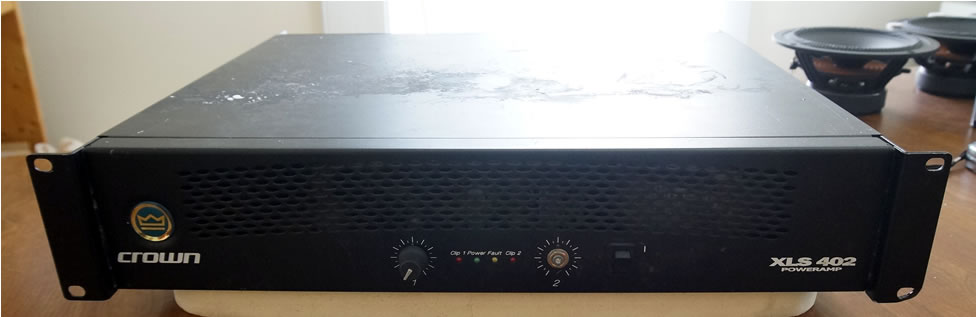
Crown XLS-402 400W 4Ω Power Amplifier
I got this Crown XLS-402 on eBay for only $13 +shipping. It looked so bad that nobody was interested. The fans at the rear were clogged with dirt. The front panel had a volume pot broken off. And obviously, no sound from both channels.
It looked so pitiful I thought to myself, if I don’t rescue it, it’ll end up in the landfill.
Crown XLS-402 Inside
On removing the top cover, I was greeted by a thick carpet of dust. That doesn’t worry me. This is not an uncommon sight in professional amps. What is important is the extend of the faults. If it’s major, then it’s not worth my time to repair it. 
Crown XLS-402 vs XLS-202
After a good vacuuming, a cursory glance shows the Crown XLS-402 has three pairs of power transistors per channel as opposed to two in the XLS-202. The power supply has been beefed up with four filter capacitors of 4,700uF/100V each. The power transformer is bigger, which is expected. Apart from these, the rest seems to be the same. It uses the same circuit board as in the XLS-202. 
Signs of Damage
Anything that’s burnt is cause for concern. With this amp, all resistors look fine on the amplifier circuit. There’s a good chance that both channels are still working. The only thing out of the ordinary is a small charred patch on the pcb where the fan control circuit is. This is the result of one of the fans dying.

Testing the Crown XLS-402
I removed the entire pcb from the case and wired it to my bench power supply for testing. I brought up the supply to +/- 85Vdc and there were no oscillations on both channels. Best of all, both outputs had no high DC. This is very promising because it indicates that all the transistors are in good working order. A word of caution. The heatsinks are not insulated. One set is at +80V while the other at -80V.

Heatsinks and Transistors
Since the pcb is on my bench, I might as well check on the health of the power transistors and their associated drivers. The power transistors MJ15024 and MJ15025 are mounted directly onto the heatsinks for best heat transfer. No mica insulators are used, only thermal compound. I removed them and the drivers MJE 5731A, TIP50 for off board testing and they were all found to be working well.
However, when I lifted the fins of the heatsink assembly, I found the thermal compound has dried and in some places, there’s not enough of it. This will weaken the effectiveness of the heatsinks. Before I reassembled the heatsinks, I applied a liberal amount of new silicon thermal compound on both the fins and the bottom plates. This will maximize the heat transfer of the power transistors.

Unexpected Issues
I reinstalled the pcb back into the case for one final test. When I connected my signal generator to the XLR inputs, horror of horrors, no outputs on both channels. Worse than that, both channels exhibited high frequency oscillations.
This cannot be. I tested the amplifier module before I screwed everything back in the case. Can it be that the new potentiometers are the culprits because when I turned off the volume, there were no oscillations. They only appear when I turned the volume pot to full.
After mulling over it for some time, I suspect the root of the problem is probably before the volume pots. The only active devices there are a couple of opamps for the balanced inputs. Could it be the opamps are dead?
I checked the supply to the opamps and true enough, one of the supply lines is dead. There is a -18V, but the +18V read 0V. So one of the zeners for the positive supplies died. This puts me in a bind. I don’t want to disassemble the entire lot again just to find a dead zener. I have better things to do with my time. Is there another way round this problem?
Modding the Inputs
The easiest solution is to do away with the balanced inputs. In doing so, no opamps are needed, meaning it doesn’t matter if one of the supplies is dead. Having decided that’s the best approach, I cut the connecting cables of the input module and de-soldered the XLR connectors.

The two XLR connectors are then screwed back to the back panel with pin2 wired directly to the main board. Pin1 is 0V which I bolted to Mains Ground. Pin3 is left open. Basically, I converted the balanced inputs to unbalanced. Normally, a RCA connector is used at the rear but out of convenience, I retained the XLR connectors. This is perfectly acceptable because in some commercial amplifiers, the XLR connectors are unbalanced internally.

Crown XLS-402 Revival
With the input conversion sorted out, it’s time to power up the Crown XLS-402 again. This time round, both channels are clean. There were no oscillations when I turned the volume pots full clockwise.

The next step is to check whether the amplification is working properly. I started with a 1kHz Sine wave and it went all the way to 160V peak to peak before clipping. That’s encouraging.
With the maximum voltage swing determined, I then injected the amplifier with a 10kHz Square wave. Unlike the XLS-202, the Crown XLS-402 displayed an overshoot. Fortunately, there’s no ringing so the amplifier is still stable.

Work Done
Considering the state of this Crown XLS-402 when she was delivered, I am quite satisfied with the outcome. I did more than just resuscitate her. I re-voiced her in the process so she is now suitable for hi-fi use.
Apart from that major change, I replaced the two volume pots at the front with new ones. She also has a new speaker binding post at the rear and a new 12V fan. I rewired the two fans for 24V operation. This will go a long way in their reliability. The heatsinks and power transistors have new thermal compound applied and lastly, I converted the inputs to unbalanced.
For an amplifier that’s destined for the dump, this Crown XLS-402 is enjoying a new lease of life.
DISCLAIMER
This article is for educational purposes only. AmpsLab takes no responsibility for any loss, injury or death howsoever caused resulting from, whether directly or indirectly, the reader’s inability to understand and appreciate the hazards of household mains or other voltages as may be applicable to any published material. All mains wiring should be performed by suitably qualified persons only. |