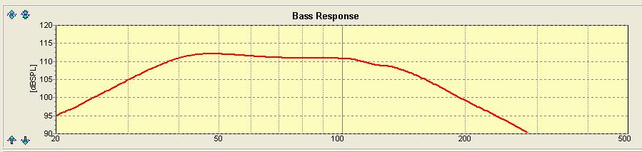
| The plot above is of my Dayton SD215A-88 DVC Subwoofer in a 4th order Bandpass box. This is the natural acoustic response taken with the mic at the mouth of the port. Corner frequencies (F3) are approximately 37Hz to 125Hz.
It is only natural to assume that if we want the Low Pass (125Hz) to be at a lower frequency, we simply set the desired frequency with an electronic crossover. Problem is, it’s not so straight forward. The plot below (Fig 1) shows the response with my electronic crossover at 100Hz (24dB/oct Linkwitz Riley). Note the in-band response is no longer flat. In fact, it’s beginning to look like a typical badly designed one note bandpass sub.  (Fig 1) Bandpass Response with electronic crossover at 100Hz (24dB/oct) The next plot (Fig 2) is with the frequency set at 150Hz. Now, the top is flatter but it’s still affected by the crossover.  (Fig 2) Bandpass Response with electronic crossover at 150Hz (24dB/oct) The final plot (Fig 3) is when my crossover is at 250Hz. We can see that the electronic crossover does not affect the top of the response. However, the slope of the Low Pass roll-off is greater.  (Fig 3) Bandpass Response with electronic crossover at 250Hz (24dB/oct) |
| Why do we want to use a crossover when a bandpass design already has a natural acoustic low pass?
Because of Noise emitting from the port. Most audible are from the midrange. By using an electronic crossover, the amplifier that’s driving the sub already has the midrange filtered out. This results in a much cleaner bandpass sub. In practical terms, the bandpass output does not smear the mids in the speaker. |
August 19, 2017Articles